Introduction
In this tutorial we will make a motorized fader work with the Arduino Uno platform.
This is the first part for making a surface controller capable of controlling volume of any channel of a virtual mixer of a DAW.
We are making this page for the closing of a final project in an engineering course.
Especially for this first part we follow the excellent Cody Hazelwood tutorial:
http://blog.codyhazelwood.me/motorized-faders-and-the-arduino/
So this will be quite similar, the next part will be more useful because there is no second tutorial on Cody’s page.
Fortunately there was code for the two parts, although it was broken, because the library dependencies had updated their API since 2012.
We only had to update the code to make it work in 2016 and we also changed the Arduino Pin Assigments for future compatibility with the MIDI tutorial (Part II).
So, here we go:
Parts Used
- Arduino Uno
- Motorized Fader
- Breadboard
- H-bridge
- External 9V DC Power supply
- 1MΩ Resistor
- 10μF Capacitor
- 10K Potentiometer
Fader
The fader used was an Alps RSA0N11M9A0J. You can find it on:
A fader is a slide potentiometer, so it works exactly like that:
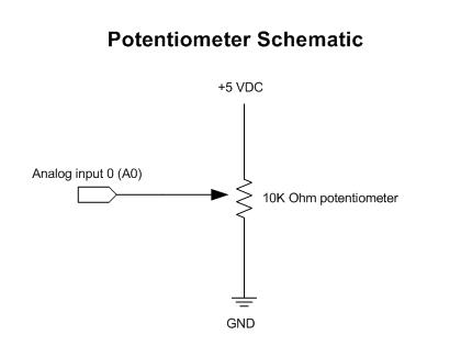
It is very easy to read the fader’s position using analogRead function: this function gets our fader’s position in the range 0-1023 (10 bit value).
To do so, we connect the fader positive pin to +5V from the Arduino, the negative to the ground and the wiper to an Analog In pin, in our case A0.
Motor Control
The fader contains a DC motor, which we will have to control.
The first thing we can try to test the motor is to supply it with 9V. Be careful because the motor can accept no more than 800 mA, you can limit current for example to 600 mA.
Connect the terminals of the motor to the positive and negative terminals of the power supply.
If we put the wiper in the midle, we can see that the wiper moves to one side of the fader when feeding the motor.
Using a digital out pin on the Arduino will give us control of the motor only in one direction, we need something for reverse the direction of the motor.
H-bridge
The device that we need is called an H-Bridge. From Wikipedia: “An H-bridge is an electronic circuit that enables a voltage to be applied across a load in either direction. These circuits are very useful to allow DC motors to run forwards and backwards”
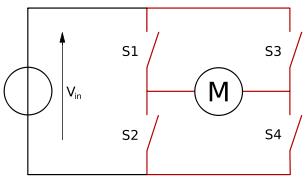
When switches S1 and S4 are turned, a positive voltage is applied to the motor, and when switches S2 and S3 are turned, a negative voltage is applied to the motor.
If S1 and S3 or S2 and S4 are turned, the motor stops.
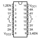
We have used a L293B H-Bridge, because it allows until 1A, but you can also use the more common L293D, which accepts current until 600mA if you limit the current like we have said before.
We will use 2 control pins, 2 output pins, a chip power in, a motor power pin and ground, depending of control pins, the motor will either go forwards, backwards, or it will stop. We can see this here:
Touch Sensitivity
Our fader is touch-sensitive, and therefore, it is not necessary to move the fader for it recognize that is being touched, and you can see the value of the fader without alter it.
Also, when we use it with a DAW , this allows to write automations with “touch-and-latch” methods, those that knows when the fader is touched, this is an important reason to use touch sensitive, other important reason is to protect the motor, to avoid situations like moving the fader and the motor moves the fader in the opposite direction, you can tell the motor using Arduino to stop while the fader is touched.
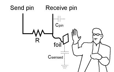
To detect when the fader is touched, we will use this library:
http://playground.arduino.cc/Main/CapacitiveSensor
We will connect 2 Arduino pin (D7 and D8) with a resistor with high value (1MΩ) between them, this converts this two pins into a capacitive sensor, which can sense the electrical capacitance of the human body, and detects when the fader is touched.
Circuit Testing
Up to this point, we will use a potentiometer for testing our circuit. Connect the wiper of the potentiometer into an Analog In pin (A3), the positive terminal to Arduino’s 5V, and the negative one to Arduino’s ground.
Using the code provided, we should see that when we move the potentiometer, the fader moves in one direction, and when we move the potentiometer in the other direction, the fader reverses its movement.
Conclusions
Until now we have focused in fader and motor performance.
In Part II, we will implement MIDI.
You can download the code and schematic below:
